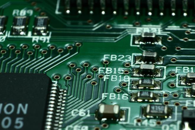
Industrial Temperature Board

Table of Contents
Temperature Sensor PCB Design #
Overview #
This project involved designing a PCB for temperature measurement using PT1000 sensors. The system features 16 channels for temperature data acquisition, signal conditioning, and filtering before interfacing with an Analog-to-Digital Converter (ADC). The PCB also includes an ST microcontroller for managing the system, analog multiplexers controlled by the MCU, and a CAN-to-USB adapter for PC communication. The design ensured high accuracy in temperature measurement and reliable data transmission.
Key Features and Achievements #
- Temperature Sensor Interface:
- Designed the interface for 16 PT1000 temperature sensors, capturing data and performing necessary signal filtering to ensure accurate readings.
- Used analog multiplexers controlled by the microcontroller to handle multiple sensor channels efficiently.
- Microcontroller Integration:
- Integrated an ST microcontroller to control the analog muxes, manage data acquisition, and process sensor information.
- Designed the circuitry necessary for programming and debugging the microcontroller.
- Signal Conditioning and ADC:
- Developed analog circuitry for signal filtering to optimize sensor data before feeding it to the ADC.
- Implemented proper analog reference generation to ensure stable and accurate ADC performance.
- CAN-to-USB Communication:
- Incorporated a CAN-to-USB adapter for seamless data transmission from the system to a PC for monitoring and analysis.
- Power Supply Design:
- Designed a multi-voltage power supply to ensure stable power delivery to the microcontroller, sensors, and other components.
Technical Details #
- Hardware Specifications:
- Temperature Sensors: 16-channel PT1000 temperature sensors for precise temperature measurements.
- Signal Conditioning: Analog filters to remove noise and prepare sensor data for ADC conversion.
- Microcontroller: ST microcontroller used to control the analog muxes and manage data processing.
- ADC: High-precision ADC for digitizing the analog signals from the sensors.
- CAN-to-USB Adapter: Used for PC interface, enabling the system to send data over CAN bus via USB.
- Design Tools:
- Cadence OrCAD for schematic design and layout guidance.
- Worked closely with the external PCB layout team to ensure signal integrity and proper component placement.
- Power Supply Design:
- Designed a multi-voltage power supply to handle different voltage requirements for the microcontroller, sensors, and peripherals.
- Created a stable analog reference for the ADC to minimize measurement errors.
Challenges and Solutions #
- Signal Integrity: Ensured clean signal acquisition through analog filtering and careful layout to avoid noise interference.
- Channel Multiplexing: Used analog multiplexers controlled by the MCU to handle multiple PT1000 sensors efficiently, ensuring correct signal routing.
- Power Management: Designed a reliable multi-voltage power supply to meet the needs of the microcontroller and sensors.
- Communication Interface: Incorporated a CAN-to-USB adapter to ensure smooth communication with a PC for monitoring and data logging.
- Programming and Debugging: Designed dedicated circuitry for microcontroller programming and debugging to streamline development and testing.
Outcome #
The PCB successfully integrated all components for high-precision temperature measurement and efficient data transmission. The design ensured accurate sensor readings, stable power delivery, and reliable communication with the PC via CAN bus. By incorporating proper signal conditioning, ADC reference generation, and robust power management, the system met all performance requirements.